AVANCE™ L3 Tray
Carlisle Interconnect Technologies is pleased to offer turnkey integration kits for the Gogo AVANCE™ L3/L5/L5i Air-To-Ground (ATG) system. These kits are ideal for all installations where customized engineering is expensive and unnecessary.
Coax and Harness kits are engineered to custom cabling lengths and connectors to match your installation needs. The trays are engineered per the Gogo specification. CarlisleIT’s engineering team is available to answer questions and provide guidance on selecting the perfect combination of components for your specific application.
| Feature | Customer Benefit |
|---|---|
| ATG, WiFi & TM Coax Cable Kits | Custom lengths, as well as fully and partially terminated coaxial cable options, are available |
| AVANCE Trays | Designed and qualified per AVANCE specifications |
| Ethernet, DataBus and USB Harness Kits | Custom length and partially terminated harnesses |
The trays are designed per the Avance system specifications; equipped with dual fans to properly cool the system, as well as a relay switch that activates the fan power when the LRU is installed. Additional custom options are available upon request.
Contact CarlisleIT engineering to confirm the right tray for your application.
P/N: 200-104609-101

P/N: 200-104624-101

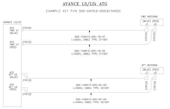
ATG coax cable kits are engineered to specify your required length and optimized for loss and attenuation dependent upon your installation length. Various cable types and connector variations (straight or right angle) are available to optimize your installation needs as both fully terminated and partially terminated options. The kits are designed for both Omni and Dual antenna configurations — just plug and play!
Example Configuration P/N: 500-104913-2001B/5405C
*For Dual Antenna Directional configuration, J4 is used instead of J2
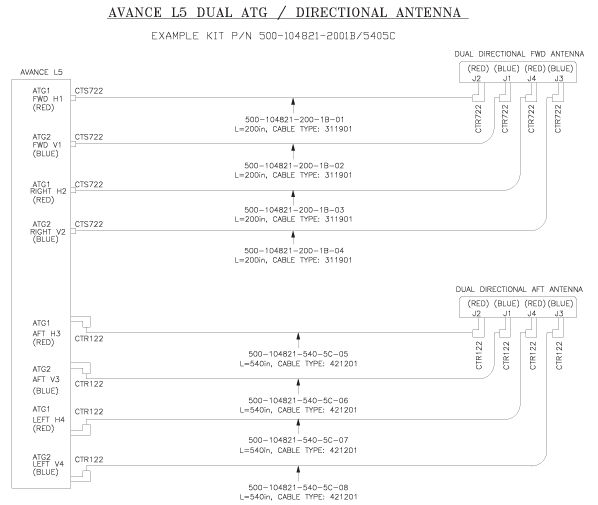
ATG coax cable kits are engineered to specify your required length and optimized for loss and attenuation dependent upon your installation length. Various cable types and connector variations (straight or right angle) are available to optimize your installation needs, as both fully terminated and partially terminated options. The kits are designed for both Omni and Dual antenna configurations — just plug and play!
Example Configuration P/N: 500-104821-2001B/5405C
Example Configuration P/N: 500-104967-2001B/2401A/5405C/2201B
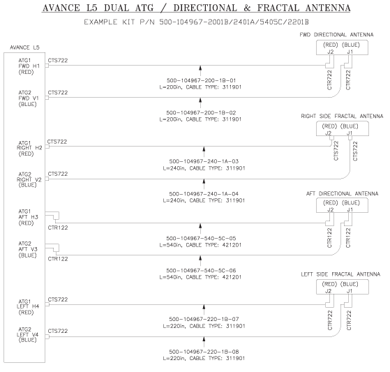
ATG coax cable kits are engineered to specify your required length and optimized for loss and attenuation dependent upon your installation length. Various cable types and connector variations (straight or right angle) are available to optimize your installation needs, as both fully terminated and partially terminated options. The kits are designed for both Omni and Dual antenna configurations — just plug and play!
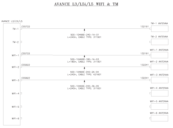
Please refer to the configurator worksheet below and linked drawing to generate your cables based on how many TM & WiFi antennas are required. SMA coax connectors are automatically chosen based on cable type and connector configuration. Cables are ordered a la carte.
Example Configuration
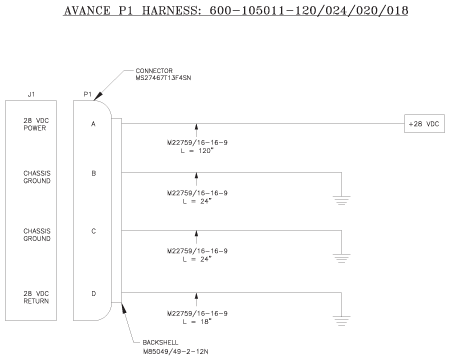
Connector harness kits are engineered to specify your desired lengths for each aircraft bus location and system specified in the installation manual. Please refer to the following worksheets to build your P1, P2, & P3 harnesses. All harnesses are terminated at the connector end and capped at the A/C end. Ethernet, DataBus, USB, & Discrete wires specified in the installation manual are used to populate the connector harnesses. The harnesses also include the mating backshells for P1, P2, & P3. Additional bulk wire & cable can be purchased separate from the harnesses to accommodate additional ethernet and databus connections needed to complete your installation.
Example Configuration P/N: 600-105011-120/024/020/018
Example Configuration P/N: 600-104968-180/144/212/048/284
*Max Length of 204 in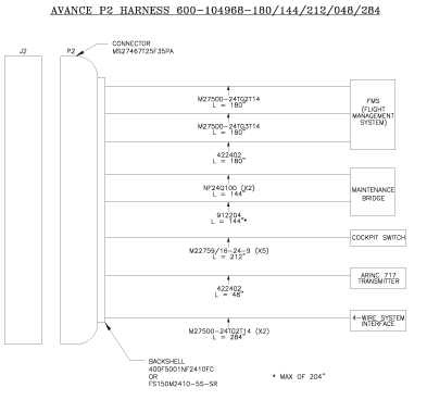
Example Configuration P/N: 600-105012-132/064/168/302/288/048
*Max Length of 204 in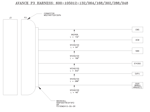
Gogo AVANCE sheet
AVANCE™ L3 Tray drawing
Drawing 900-104961
AVANCE™ L5/L5i Tray drawing
Drawing 900-104969
L3/L5i ATG Coax Kit Product Information
Drawing 500-104913
L3/L5i ATG Configurator Worksheet
Dual ATG/Directional Antenna
Drawing 500-104821
L5 Dual ATG/Directional Antenna Configurator Worksheet
Dual ATG/Directional and Fractal Antenna
Drawing 500-104669
WiFi & TM Configurator Worksheet
P1 Harness
Drawing 600-105011
P1 Harness Configurator Worksheet
P2 Harness
Drawing 600-104968
P2 Harness Configurator Worksheet
P3 Harness
Drawing 600-105012
P3 Harness Configurator Worksheet
To inquire about Gogo AVANCE Systems Kits available from CarlisleIT, please fill out the form below, and one of our Sales Engineers will contact you.
"*" indicates required fields